
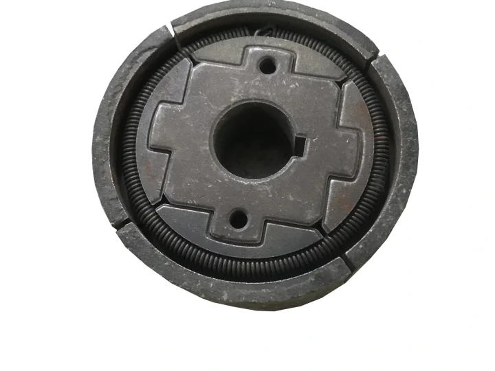
Tamping Rammer Engine Clutch
This replacement clutch connects an engine to a rammer drive. The photographs show the clutch face, central bore and related loose components, not a complete replacement engine.
View product →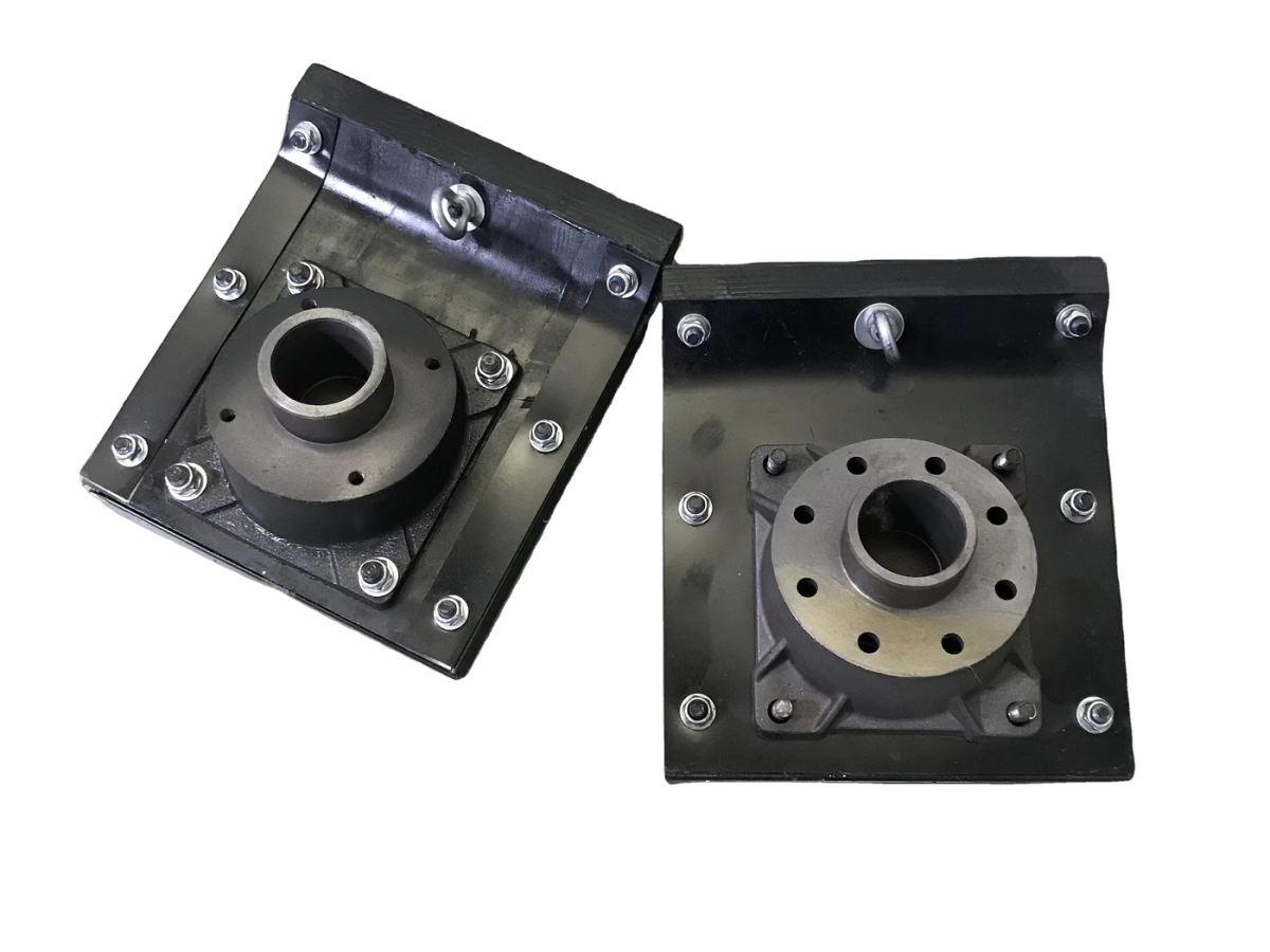
Model to be confirmed
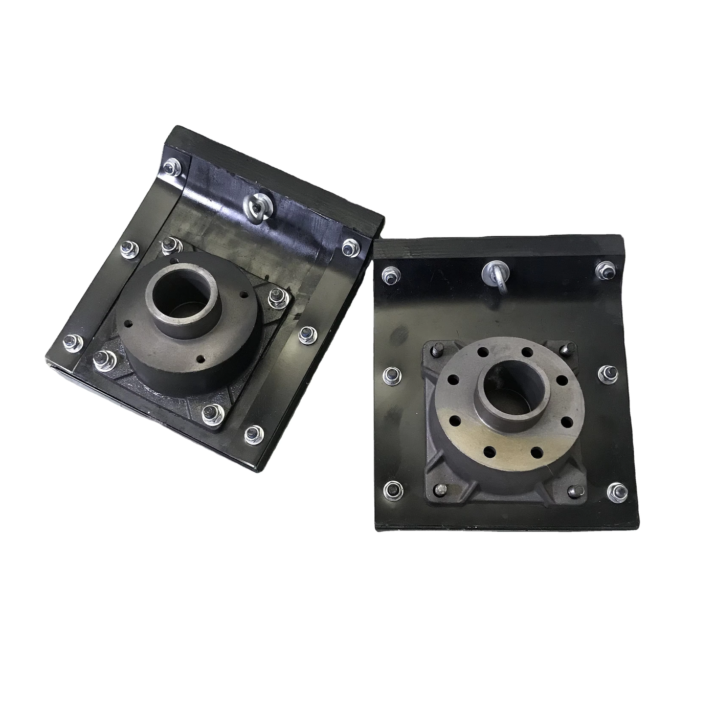
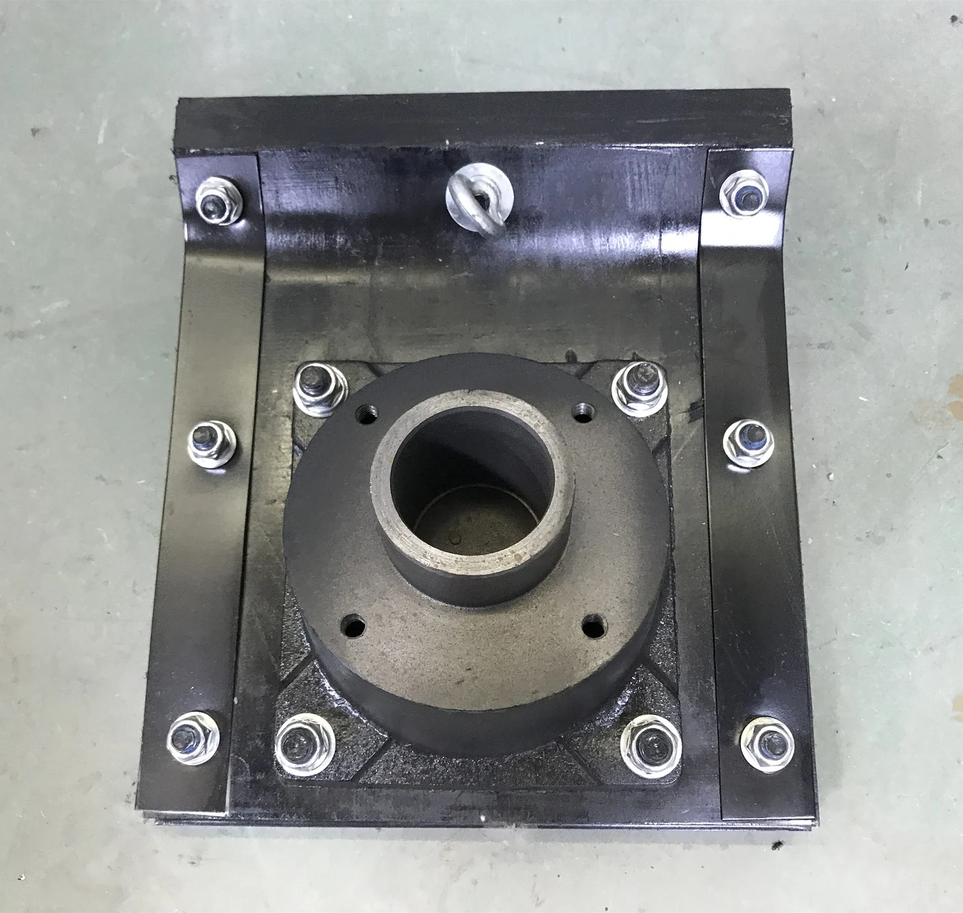
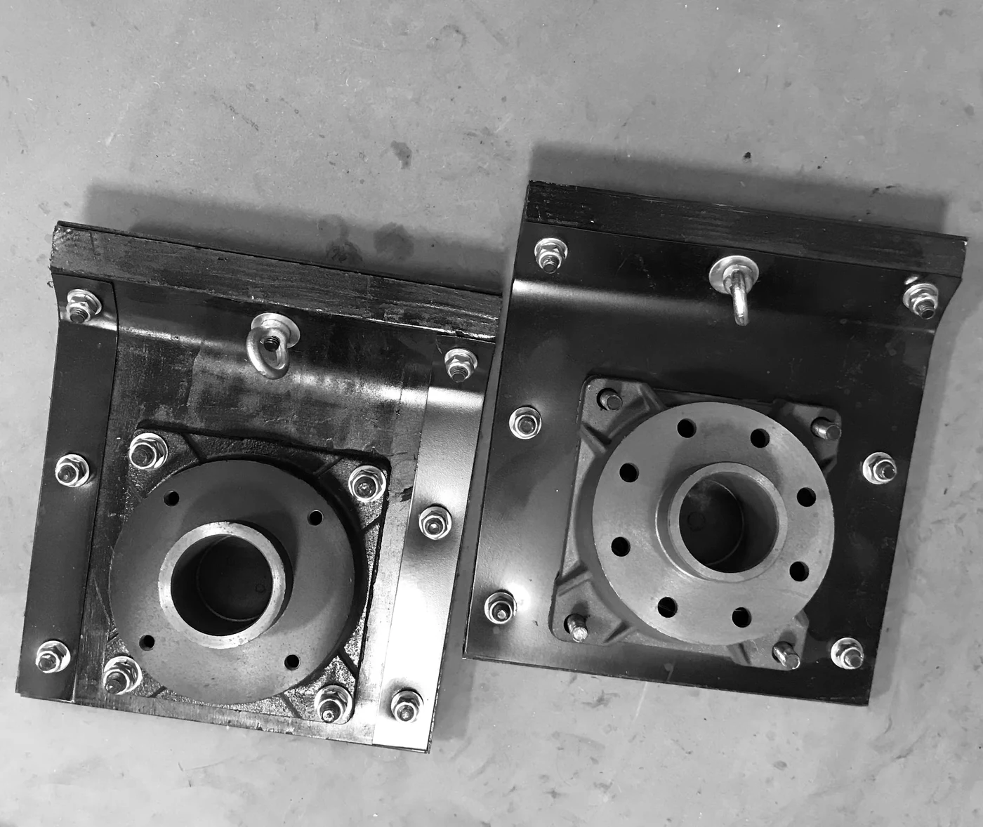
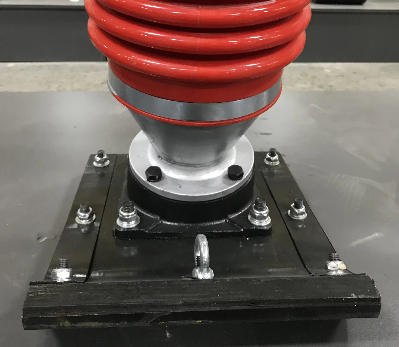
A replacement shoe assembly for an impact/tamping rammer. The supplied images show the foot, central mounting interface and fasteners. Replacement selection should match the existing machine and mounting geometry, rather than just the outside foot size.
| Part description | Rammer shoe / foot assembly |
|---|---|
| Listed machine type | Impact rammer |
| Source size designations | 250 × 330 / 280 × 330 / 300 × 330 — Units and variant mapping are absent in the original field; not a confirmed dimension drawing. |
| Source weight entry | 9.5 kg — Not assigned to each size; confirm the selected assembly’s net weight. |
The shoe is the ground-contact assembly at the bottom of the rammer. The supplied views show rectangular feet, a raised central mounting interface and several fastening positions. They help identify the part arrangement, but do not establish an interchangeable mounting pattern for every rammer.
The current enquiry concerns the shoe assembly, not a complete rammer. A photograph showing it installed is a mounting reference only. It does not promise that a complete machine, bellows or upper rammer mechanism is included.
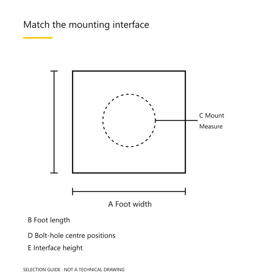
The source lists three size designations: 250 × 330, 280 × 330 and 300 × 330. It does not explicitly give units or associate each designation with a drawing. These numbers are therefore retained as supplier references rather than converted into guaranteed millimetre dimensions.
The listed 9.5 kg is not tied to each size. Material grade, layer thickness, mounting-bore diameter and exact compatible models are also absent. An approved drawing and selected-assembly weight are more useful than a long table of guessed values.
Photographs of a damaged foot can help identify the replacement scope: foot wear, deformation, missing fasteners or a damaged mounting interface may involve different parts. They are not a remote safety diagnosis. Inspection, replacement and tightening requirements must follow the applicable machine manual and a competent technician’s assessment.
For a distributor enquiry, group quantities by confirmed machine/part reference, not simply by size label. Request unit packing, corrosion protection, net/gross weight and the included-items list for each selected assembly.
Machine plate; old part number; measured mounting dimensions; photos; quantity; destination city.
No exact compatibility has been verified from the available shoe listing. A related-machine image does not prove fit. Compare the mounting drawing, old part and exact machine identity first.
That has not been established. The source gives one weight entry without a size-to-weight mapping. Confirm the selected assembly’s net weight separately.
Clear top, underside and side views of the existing foot, a close mounting-interface view, marked measurements and the machine plate. Include the old part number if available.
This replacement clutch connects an engine to a rammer drive. The photographs show the clutch face, central bore and related loose components, not a complete replacement engine.
View product →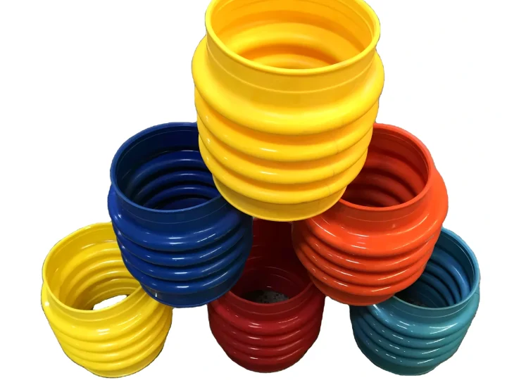
This flexible bellows surrounds the moving lower assembly of a tamping rammer. The original photographs show its corrugations and end openings in several colours; colour is not a reliable compatibility code.
View product →This listing shows a clutch assembly and separate circular plates for a rammer engine drive. The group photograph helps compare faces and openings; it is not proof that every pictured piece belongs to the quoted set.
View product →